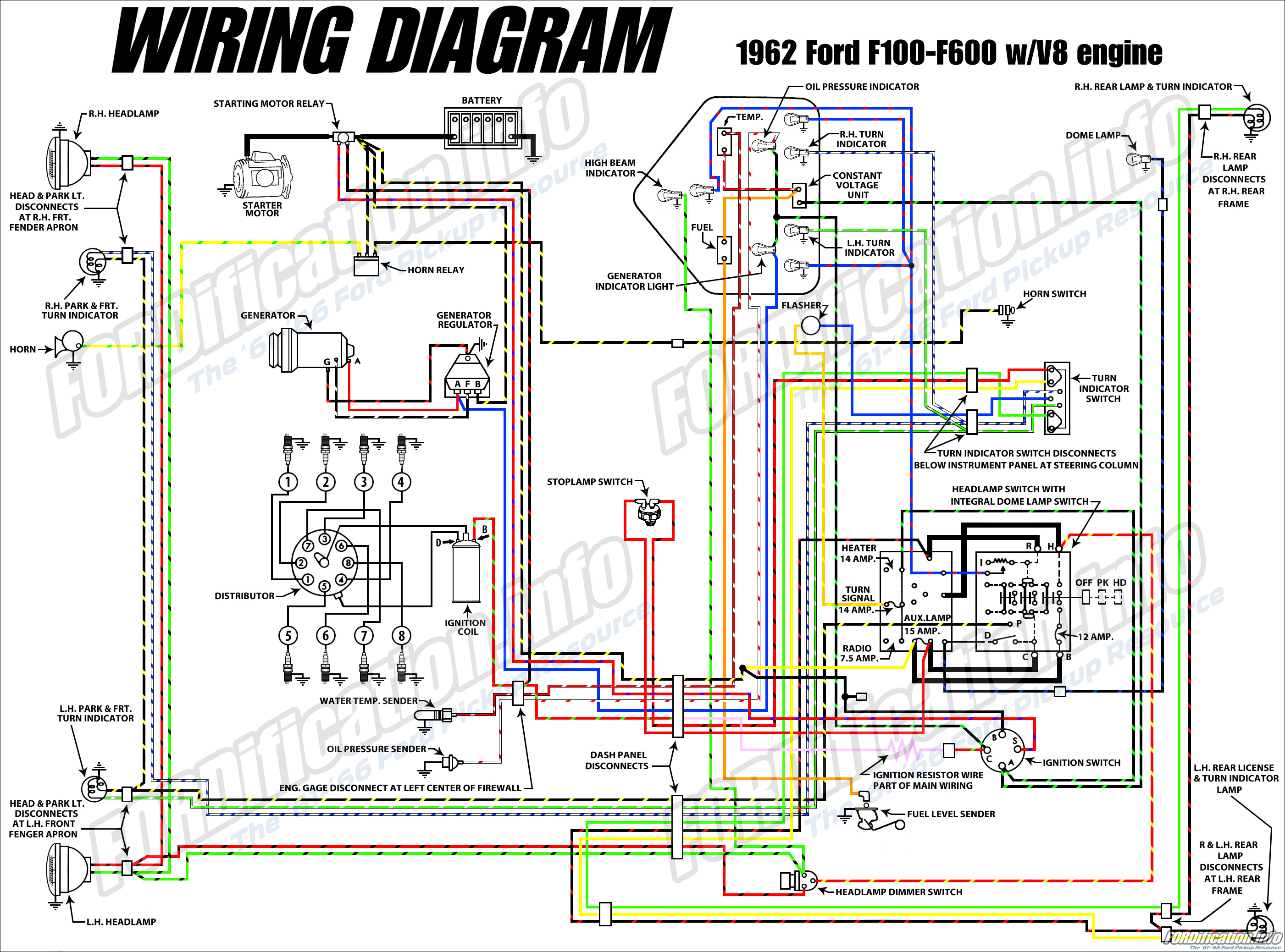
1970 Ford F100 Alternator Wiring Diagram
When it comes to working on your 1970 Ford F100’s electrical system, having a clear understanding of the alternator wiring diagram is essential. This diagram serves as a roadmap for the electrical connections within the alternator system, ensuring proper functioning and troubleshooting when issues arise.
Why are 1970 Ford F100 Alternator Wiring Diagrams Essential?
- Helps identify the various components within the alternator system
- Guides proper installation and connection of wires
- Aids in diagnosing electrical issues and troubleshooting problems
How to Read and Interpret 1970 Ford F100 Alternator Wiring Diagrams
Reading and interpreting wiring diagrams can seem daunting at first, but with a bit of practice, it becomes much clearer. Here are some tips:
- Start by familiarizing yourself with the key symbols and color codes used in the diagram
- Follow the flow of the wiring from one component to the next
- Pay attention to the connections and wire colors specified in the diagram
Using Wiring Diagrams for Troubleshooting Electrical Problems
When faced with electrical issues in your 1970 Ford F100, referring to the alternator wiring diagram can be a lifesaver. Here’s how you can use it for troubleshooting:
- Identify the specific circuit or component that is causing the problem
- Trace the wiring to check for any loose connections or damaged wires
- Compare the diagram to the actual wiring to ensure everything is connected correctly
Importance of Safety When Working with Wiring Diagrams
Working with electrical systems can be dangerous if proper precautions are not taken. Here are some safety tips to keep in mind:
- Always disconnect the battery before working on any electrical components
- Avoid working on the electrical system in wet or damp conditions
- Use insulated tools to prevent electric shocks
- If you’re unsure about a particular wiring connection, consult a professional mechanic
1970 Ford F100 Alternator Wiring Diagram
1970 Ford F100 Alternator Wiring Diagram

1970 Ford F100 Alternator Wiring Diagram – Easy Wiring

1970 Ford F100 Alternator Wiring Diagram – Easy Wiring

1970 Ford Alternator Wiring Diagram – Collection – Faceitsalon.com

20+ 1970 Ford F100 Alternator Wiring Diagram Gif | daseratuiop
1970 Ford F100 Wiring Diagram Collection – Wiring Diagram Sample
