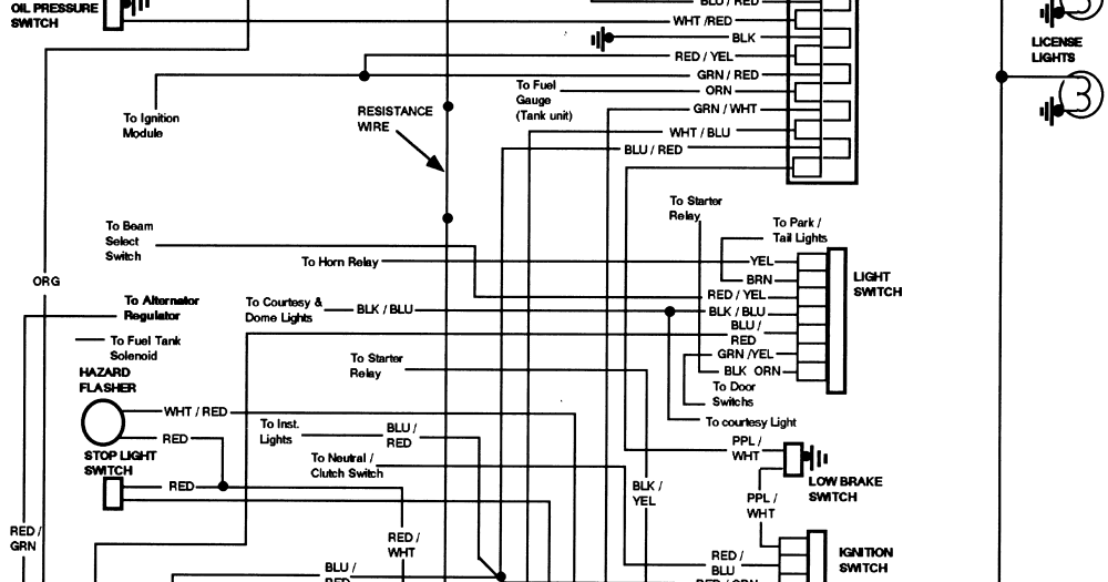
1979 Ford F150 Turn Signal Wiring Diagram
When it comes to working on a classic 1979 Ford F150, having access to the turn signal wiring diagram is essential for any mechanic or DIY enthusiast. Understanding how the turn signal system is wired can help you diagnose and fix any electrical issues that may arise.
Why are 1979 Ford F150 Turn Signal Wiring Diagrams Essential?
- Helps in identifying the components of the turn signal system
- Allows for proper installation of new turn signal components
- Aids in troubleshooting any electrical issues
- Ensures the safety and proper functioning of the turn signal system
How to Read and Interpret 1979 Ford F150 Turn Signal Wiring Diagrams Effectively
- Start by familiarizing yourself with the symbols used in the diagram
- Follow the color-coded lines to trace the wiring from the battery to the turn signals
- Identify the different components such as fuses, relays, switches, and lights
- Refer to the legend for any specific codes or abbreviations used in the diagram
Using 1979 Ford F150 Turn Signal Wiring Diagrams for Troubleshooting
- Locate the specific section of the diagram related to the turn signal system
- Check for any breaks or damage in the wiring that may be causing the issue
- Test the connections using a multimeter to ensure continuity
- Refer to the diagram to identify any faulty components that may need to be replaced
It is important to note that when working with electrical systems and using wiring diagrams, safety should always be a top priority. Here are some safety tips and best practices to keep in mind:
- Always disconnect the battery before working on any electrical components
- Use insulated tools to prevent any risk of electric shock
- Avoid working on electrical systems in wet or damp conditions
- Double-check your work and ensure all connections are secure before testing the system
1979 Ford F150 Turn Signal Wiring Diagram
1979 Ford F150 Turn Signal Wiring Diagram – Naturalfer

1979 Ford F150 Wiring Diagram

Ford F150 Turn Signal Wiring Diagram – Wiring Diagram

1979 Ford F150 Wiring Diagram Collection

[DIAGRAM] 1979 F150 Turn Signal Diagram – MYDIAGRAM.ONLINE
![1979 Ford F150 Turn Signal Wiring Diagram [DIAGRAM] 1979 F150 Turn Signal Diagram - MYDIAGRAM.ONLINE](https://i1.wp.com/ww2.justanswer.com/uploads/bkitchener/2011-08-13_153114_94_econoline.png)
1979 Ford Truck Wiring Diagrams
