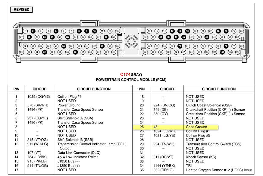
1999 Ford Ranger Pcm Wiring Diagram
When it comes to working on your 1999 Ford Ranger, having access to the PCM wiring diagram is essential. The PCM (Powertrain Control Module) is a vital component of your vehicle’s engine management system, and understanding its wiring diagram can help you diagnose and troubleshoot electrical issues effectively.
Why are 1999 Ford Ranger Pcm Wiring Diagrams Essential?
- Helps identify the location of components and connections within the PCM system
- Allows for easy tracing and testing of wires for continuity and voltage
- Aids in diagnosing issues related to sensors, actuators, and other components connected to the PCM
How to Read and Interpret 1999 Ford Ranger Pcm Wiring Diagrams
- Start by understanding the key symbols and color codes used in the diagram
- Follow the flow of the wiring diagram from the power source to the components
- Pay attention to the connectors, wires, and grounds to ensure proper connections
Using 1999 Ford Ranger Pcm Wiring Diagrams for Troubleshooting Electrical Problems
- Identify the specific circuit or component that is malfunctioning
- Check for continuity, voltage, and resistance at various points in the circuit
- Compare the actual readings with the values specified in the wiring diagram
It is important to note that safety should always be a top priority when working with electrical systems and wiring diagrams. Here are some safety tips to keep in mind:
- Always disconnect the battery before working on any electrical components
- Use insulated tools to prevent the risk of electric shock
- Avoid working on wet surfaces or in damp conditions to prevent short circuits
- If you are unsure about any aspect of the wiring diagram, consult a professional mechanic for assistance
1999 Ford Ranger Pcm Wiring Diagram
1999 Ford Ranger System Wiring Diagrams | 4 Images | Wiring Diagrams Center

1999 Ford Ranger Pcm Wiring Diagram Images – Faceitsalon.com

1999 Ford Ranger Pcm Wiring Diagram Images – Faceitsalon.com

Ford Ranger Wiring Diagram 1999 – diagram wiring plc
