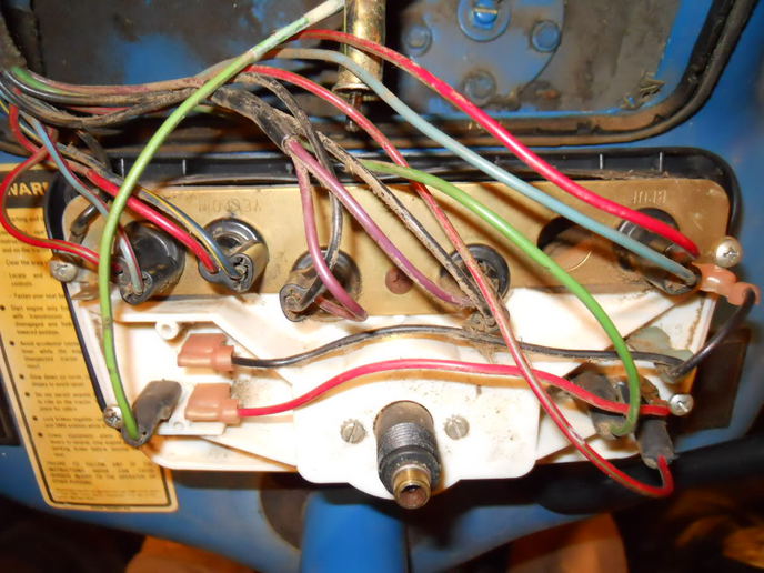
Ford 5000 Instrument Cluster Wiring Diagram is a crucial tool for understanding the electrical system of the Ford 5000 tractor. This diagram provides a visual representation of the wiring connections within the instrument cluster, helping mechanics and technicians to troubleshoot and repair electrical issues effectively.
Importance of Ford 5000 Instrument Cluster Wiring Diagram
Here are some reasons why Ford 5000 Instrument Cluster Wiring Diagrams are essential:
- Provide a clear overview of the electrical connections in the instrument cluster
- Help in identifying faulty wiring or components
- Aid in the installation of new electrical components
- Enable efficient troubleshooting of electrical problems
Reading and Interpreting Ford 5000 Instrument Cluster Wiring Diagram
Understanding how to read and interpret the wiring diagram is crucial for effective troubleshooting. Here are some tips:
- Identify the symbols and colors used in the diagram
- Follow the flow of the wiring from one component to another
- Pay attention to the connection points and wire routing
- Refer to the legend or key for explanations of symbols and colors
Using Ford 5000 Instrument Cluster Wiring Diagram for Troubleshooting
When faced with electrical problems in the Ford 5000 tractor, the wiring diagram can be a valuable resource for troubleshooting. Here’s how it can help:
- Locate the specific circuit or component causing the issue
- Check for continuity and voltage at various points in the circuit
- Compare the actual wiring with the diagram to identify discrepancies
- Follow a systematic approach to isolate and resolve the problem
Importance of Safety
Working with electrical systems can be hazardous, so it’s essential to prioritize safety. Here are some safety tips when using wiring diagrams:
- Always disconnect the battery before working on the electrical system
- Use insulated tools to prevent electric shocks
- Avoid working on electrical components in wet or damp conditions
- Double-check all connections before reapplying power
Ford 5000 Instrument Cluster Wiring Diagram
Ford 5000 Instrument Cluster Wiring Diagram

[21+] Ford 5000 Instrument Cluster Wiring Diagram, Instrument Cluster
![Ford 5000 Instrument Cluster Wiring Diagram [21+] Ford 5000 Instrument Cluster Wiring Diagram, Instrument Cluster](https://i1.wp.com/i.imgur.com/0evd61U.jpg)
[21+] Ford 5000 Instrument Cluster Wiring Diagram, Instrument Cluster
![Ford 5000 Instrument Cluster Wiring Diagram [21+] Ford 5000 Instrument Cluster Wiring Diagram, Instrument Cluster](https://i1.wp.com/ww2.justanswer.com/uploads/djenn434/2009-11-25_210934_radio_0000.jpg)
[21+] Ford 5000 Instrument Cluster Wiring Diagram, Instrument Cluster
![Ford 5000 Instrument Cluster Wiring Diagram [21+] Ford 5000 Instrument Cluster Wiring Diagram, Instrument Cluster](http://i1303.photobucket.com/albums/ag153/Jake_Putnik/componetlocations1of8_zpsa1bb7e3c.gif)
[21+] Ford 5000 Instrument Cluster Wiring Diagram, Instrument Cluster
![Ford 5000 Instrument Cluster Wiring Diagram [21+] Ford 5000 Instrument Cluster Wiring Diagram, Instrument Cluster](http://i293.photobucket.com/albums/mm45/6054Ken_C/97 F250 HD 73 powerstroke 4x4 cc sb e4od auto/InstrumentClusterIllumination.jpg)
Ford 3000 Instrument Panel Wiring – Yesterday's Tractors
