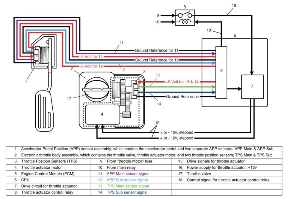
When it comes to diagnosing and repairing electrical issues in your Ford vehicle, having a thorough understanding of the Ford Throttle Position Sensor Wiring Diagram is crucial. This diagram provides a visual representation of the wiring and connections for the throttle position sensor, allowing you to easily identify and troubleshoot any issues that may arise.
Why are Ford Throttle Position Sensor Wiring Diagrams essential?
Understanding the Ford Throttle Position Sensor Wiring Diagram is essential for several reasons:
- Helps identify the correct wiring connections for the throttle position sensor
- Allows for easy troubleshooting of electrical issues related to the sensor
- Ensures proper installation and maintenance of the sensor
How to read and interpret Ford Throttle Position Sensor Wiring Diagrams effectively
Reading and interpreting the Ford Throttle Position Sensor Wiring Diagram may seem daunting at first, but with the right guidance, it can be a straightforward process. Here are some tips to help you:
- Identify the key components of the diagram, such as the sensor, connectors, and wiring colors
- Follow the wiring paths to understand how the sensor is connected to the vehicle’s electrical system
- Refer to the legend or key provided with the diagram to understand the symbols and abbreviations used
Using Ford Throttle Position Sensor Wiring Diagrams for troubleshooting electrical problems
When faced with electrical issues related to the throttle position sensor, the wiring diagram can be a valuable tool for troubleshooting. Here’s how you can use it effectively:
- Check for continuity and proper voltage levels at the sensor connections
- Trace the wiring paths to identify any damaged or corroded wires that may be causing the issue
- Compare the actual wiring connections to the diagram to ensure they match up correctly
Safety tips and best practices
Working with electrical systems can be dangerous if proper precautions are not taken. When using Ford Throttle Position Sensor Wiring Diagrams, always remember to:
- Disconnect the vehicle’s battery before working on any electrical components
- Use insulated tools to prevent electrical shock
- Avoid working on the vehicle in wet or damp conditions
- Double-check all connections before powering up the vehicle
Ford Throttle Position Sensor Wiring Diagram
Ford Throttle Position Sensor Wiring Diagram – Artsian

Ford Throttle Position Sensor Diagram

Ford Throttle Position Sensor Wiring Diagram – parleyinspire

Ford Throttle Position Sensor Wiring Diagram

ford throttle position sensor wiring diagram Wiring throttle

2008 F250 5.4 Throttle Position Sensor Wiring Diagram
