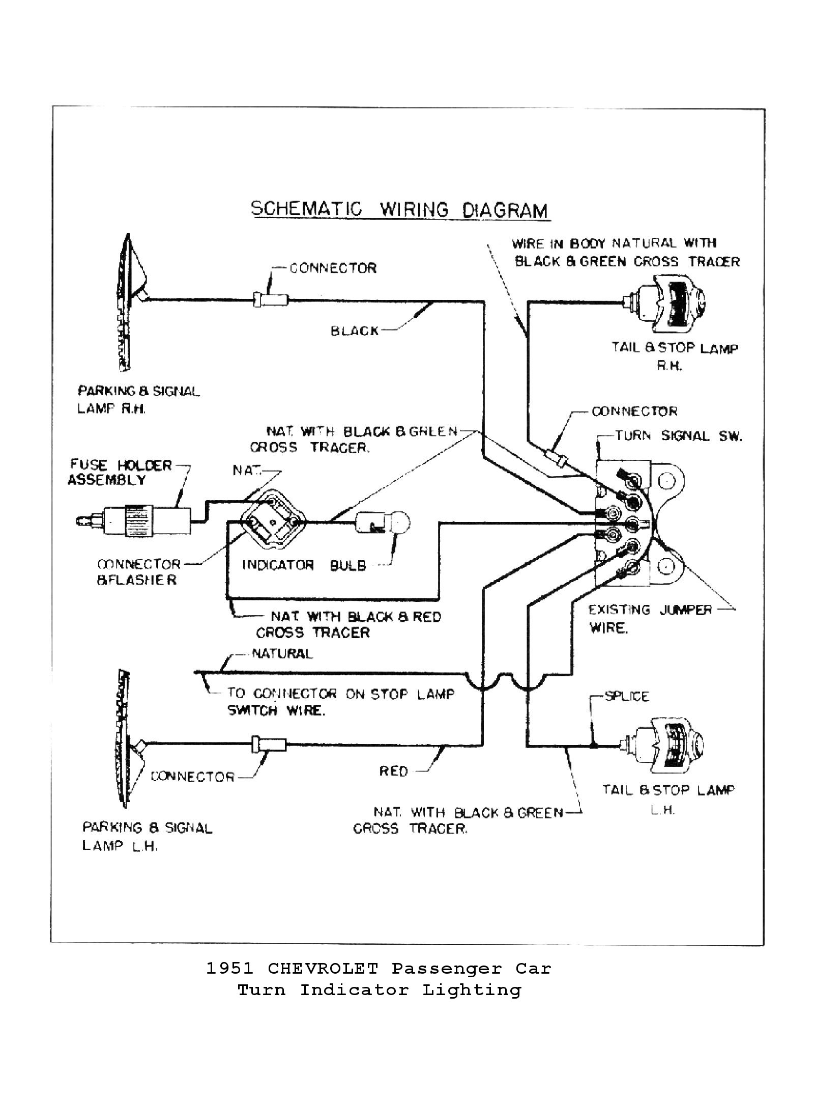
Model A Ford Turn Signal Wiring Diagrams are essential tools for understanding the electrical system of a Model A Ford. By studying these diagrams, mechanics and car enthusiasts can gain a better understanding of how the turn signal wiring is configured and connected within the vehicle.
Importance of Model A Ford Turn Signal Wiring Diagrams
- Help in identifying the various components of the turn signal system
- Show the wiring connections and routes for the turn signal system
- Aid in troubleshooting and diagnosing electrical issues
- Ensure proper installation and maintenance of the turn signal system
Reading and Interpreting Model A Ford Turn Signal Wiring Diagrams
When looking at a Model A Ford Turn Signal Wiring Diagram, it’s important to understand the symbols and conventions used. Typically, lines represent wires, while symbols represent components such as switches, bulbs, and connectors. Color-coding may also be used to differentiate between different wires.
Using Model A Ford Turn Signal Wiring Diagrams for Troubleshooting
- Identify the specific circuit or component causing the issue
- Follow the wiring diagram to trace the path of the electrical current
- Check for continuity, shorts, or open circuits using a multimeter
- Refer to the wiring diagram to make necessary repairs or replacements
Importance of Safety
When working with electrical systems and using wiring diagrams, it’s crucial to prioritize safety to prevent accidents and injuries. Here are some safety tips and best practices to keep in mind:
- Always disconnect the battery before working on any electrical components
- Use insulated tools to avoid electric shocks
- Avoid working on electrical systems in wet or damp conditions
- Double-check connections and wiring before restoring power to the system
Model A Ford Turn Signal Wiring Diagram
Ford Turn Signal Switch Wiring Diagram – Colorin

Ford Turn Signal Switch Wiring Diagram
Ford Turn Signal Wiring Diagram Collection – Faceitsalon.com

Ford F100 Turn Signal Switch Wiring Diagram

Turn signal switch wiring – Ford Truck Enthusiasts Forums

Ford Turn Signal Flasher Diagram
